Flow and pressure describe different parts of irrigation performance. A flow meter quantifies delivery through a pipe; pressure measurements show the hydraulic conditions available to filters, valves and emitters. Recording both at known locations makes a supply fault, restriction or unexpected demand easier to distinguish.
Flow rate, accumulated volume and hydraulic pressure
Flow rate is volume per unit time, commonly litres per second or cubic metres per hour. Totalised volume integrates that rate over an irrigation event. A steady 12 m³/h for 45 minutes delivers 9 m³ through the meter. Spread uniformly over 0.5 hectares, that volume corresponds to 1.8 mm of gross applied depth. This calculation describes metered delivery; evaporation, distribution losses and non-uniform application affect the water reaching individual roots.
Gauge pressure is pressure relative to local atmospheric pressure. A bar is 100 kPa and corresponds to approximately 10.2 metres of freshwater head. Pressure at the pump discharge, after filtration and at the block inlet answers different questions. A single pressure transmitter cannot describe the pressure drop across a filter unless a second measurement or differential instrument supplies the other side.
Meters and transmitters for irrigation infrastructure
The instruments below cover full-bore electromagnetic metering, compact metering and pressure feedback. Flow meters compete for the delivery measurement; pressure transmitters complement them. Pipe diameter, operating velocity, electrical conductivity, connection type and signal interface determine whether an instrument fits a particular installation.
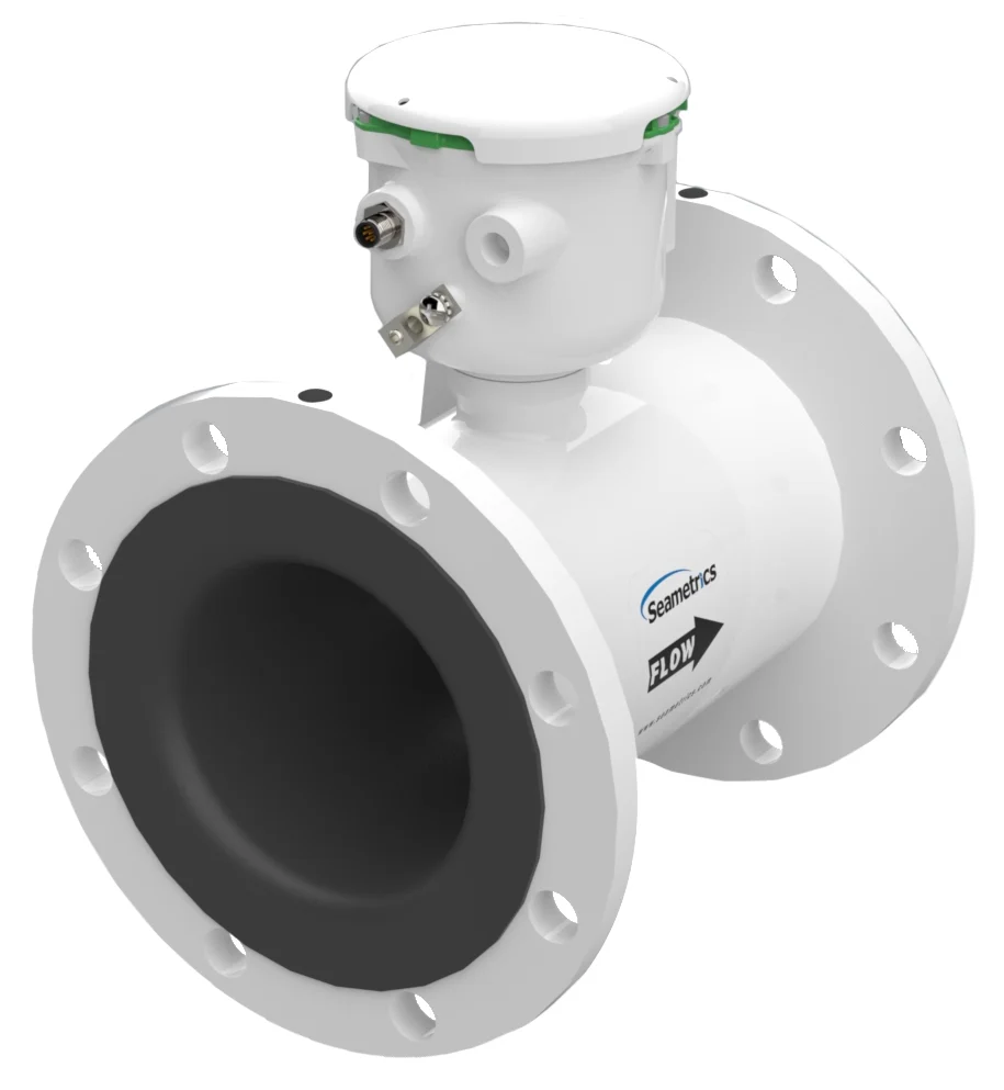
Flanged electromagnetic irrigation meter
Seametrics AG3000
A full-bore meter without moving measuring parts, with local rate and total display. Battery and externally powered versions address different telemetry requirements.
Full-pipe installation and selected power/output variant must match the project.
View product details ↗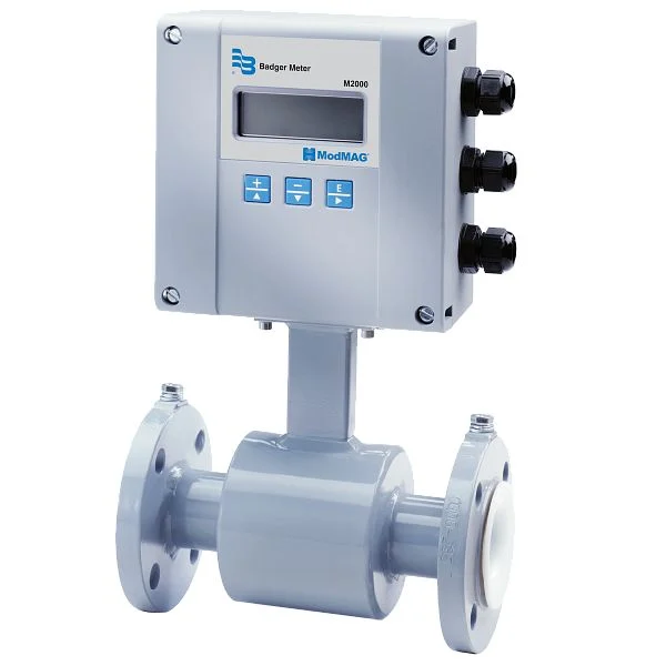
Configured detector and amplifier
Badger Meter ModMAG M2000
An electromagnetic meter with a broad selection of detector sizes and materials. Its specified accuracy depends on installation, with a separate reduced-straight-run specification.
Power, materials and straight-run conditions are configuration-dependent.
View product details ↗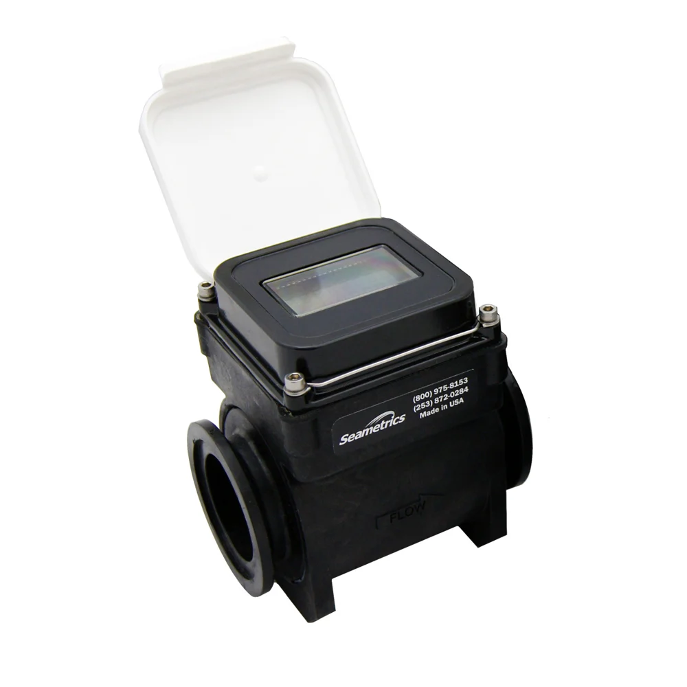
Plastic-bodied electromagnetic meter
Seametrics WMP-Series
A battery-powered electromagnetic meter for smaller installations. The absence of moving measuring parts is useful where debris would interfere with a mechanical rotor.
Confirm pressure, temperature, pipe size and chemical compatibility.
View product details ↗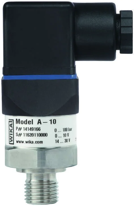
Configured industrial pressure transmitter
WIKA A-10
A compact pressure transmitter that complements flow measurement. Its configurable span and signal options allow connection to suitable analogue instrumentation.
Water-compatible range, wetted materials, overload limits and connector need specification.
View product details ↗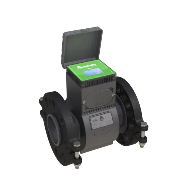
Composite electromagnetic flow meter
BERMAD M10
A composite-bodied electromagnetic meter for agricultural and water distribution installations. The manufacturer describes a calibrated full-bore measurement path without a mechanical rotor.
Confirm the process connection and the meter’s complete power/output package.
View product details ↗| Model | Measurement / role | Data connection | Coverage / installation |
|---|---|---|---|
| Seametrics AG3000 | Flow rate and accumulated volume | Pulse; selected externally powered output options | 2–12 inch line sizes |
| Badger Meter ModMAG M2000 | Bidirectional liquid flow | RS232 Modbus RTU; other protocols need daughterboards | Size and lining selected for the pipe and water |
| Seametrics WMP-Series | Flow rate and accumulated volume | Pulse output and local display | Smaller-pipe irrigation and water systems |
| WIKA A-10 | Gauge, absolute or vacuum pressure by variant | 4–20 mA or voltage output by configuration | Pressure span and process fitting selected to suit the line |
| BERMAD M10 | Bidirectional flow and volume | Power and outputs depend on the ordered configuration | DN50–DN150 family; selected connection configuration |
Electromagnetic, mechanical and pressure sensing
Electromagnetic meters use the voltage induced as a conductive liquid moves through a magnetic field. Electrodes detect that voltage, and the instrument converts velocity into volumetric flow using its calibrated geometry. The pipe must remain full. Air pockets and poorly grounded installations can disturb the reading even when the display continues to show a plausible number.
Mechanical meters infer volume from the motion of an impeller, turbine or other moving element. Their installation and maintenance depend on suspended solids, minimum flow and bearing condition. An electromagnetic meter removes the rotating element, but still requires compatible wetted materials and water conductivity. Insertion meters measure locally within the pipe rather than across an entire calibrated spool; insertion depth and flow profile become especially important.
Pressure transmitters convert diaphragm deformation into an electrical signal. Select the pressure span to include normal operation and foreseeable surges without sacrificing useful resolution. A quoted percentage of full span produces a fixed pressure uncertainty; a percentage of reading scales with the current measurement. Those specifications should remain separate when comparing instruments.
Installation conditions that affect the record
The manufacturer’s straight-run requirements apply to the selected meter and configuration. Elbows, partly closed valves and pumps disturb the velocity profile. A reduced straight-run installation may have a different accuracy specification, as Badger Meter explicitly describes for the M2000. An instrument advertised for tight spaces does not remove the need to check its installation drawing.
Position pressure taps so trapped air, sediment and vibration can be managed. Record the elevation of each point when comparing readings across a sloping farm. A lower instrument may show higher static pressure simply because of elevation. Fit suitable isolation and servicing arrangements so a failed transducer can be replaced without unnecessarily interrupting the entire water network.
Pulse outputs need a declared volume per pulse. The receiving counter must support the pulse width and maximum frequency. For a 4–20 mA transmitter, the logger’s configured engineering range must match the instrument’s range; 12 mA represents the midpoint only after both ends use the same scaling. Record units in the exported data rather than relying on dashboard labels.
Interpreting combined flow and pressure
A high-flow event with falling downstream pressure can indicate an additional open demand or a damaged line. Low flow with high upstream pressure can indicate a closed valve or restriction. Low flow and low supply pressure can reflect source or pump limitations. These patterns are diagnostic leads, not unique fault signatures. Valve state, pump state and the normal operating combination of blocks provide the context.
Establish reference flow and pressure for each relevant valve combination after commissioning. Include the delay while pipes fill and pressure stabilises. An alarm based on the first seconds after valve opening can confuse a normal transient with a fault. Preserve event totals and raw observations so an unexplained discrepancy can be investigated later.
From local registers to hydraulic records
Mechanical volume registers provided local accumulated water measurements before electronic instruments added signal outputs and automated logging. Electromagnetic meters use the induction principle established by Faraday in the nineteenth century. Connected irrigation extends the measurement path to controllers and remote records; the hydraulic installation still determines what each reading represents.
- Head loss
- The reduction in hydraulic energy through a pipe, fitting, filter or valve, expressed as a pressure difference or metres of head.
- Totaliser
- A register of accumulated volume passing through a meter.
- Pulse factor
- The relationship between pulse count and measured volume, such as litres per pulse.
- Full span
- The difference between the configured upper and lower measurement limits.
Questions about irrigation measurements
Does a pressure reading prove that a block received its scheduled volume?
No. Pressure confirms a hydraulic condition at one location. A suitable flow meter and event total provide evidence of volume delivered through the measured pipe.
Can one mainline meter identify the failed lateral?
It can reveal a changed total demand. Identifying the location requires valve-state information, sectional measurements or inspection of the affected block.
Should the smallest available meter be selected for low flow?
Assess the full expected flow range and allowable head loss. A smaller meter can improve velocity at low demand but constrain peak flow or increase pressure loss.