Level instruments quantify the water surface relative to a defined reference. The appropriate method depends on whether the installation is a tank, open reservoir, channel or borehole, and on access, surface conditions and the required record. Radar, ultrasound and submerged pressure sensing solve different installation problems.
Distance, level and stored volume
A non-contact instrument measures distance from its reference point to the water surface. Water level is calculated from that distance and a surveyed reference elevation or tank geometry. A smaller measured distance corresponds to a higher surface when the sensor is mounted above the water. The displayed level must retain its datum when the instrument is moved or replaced.
Stored volume requires a relationship between level and vessel shape. In a vertical tank with a constant 20 m² cross-section, a 0.1 m change in level represents 2 m³. A sloping reservoir or horizontal cylindrical tank needs a different level-volume curve. Sensor accuracy alone does not establish volume accuracy if the geometry is uncertain.
Six level-measurement options
The instruments below include three free-space radar options, ultrasonic ranging, guided radar and a submerged pressure logger. Compare them by installation geometry and exposure. Guided radar uses a probe extending into the vessel; it should not be confused with a free-space radar mounted above an open surface.
PCSKRDR; selected housing
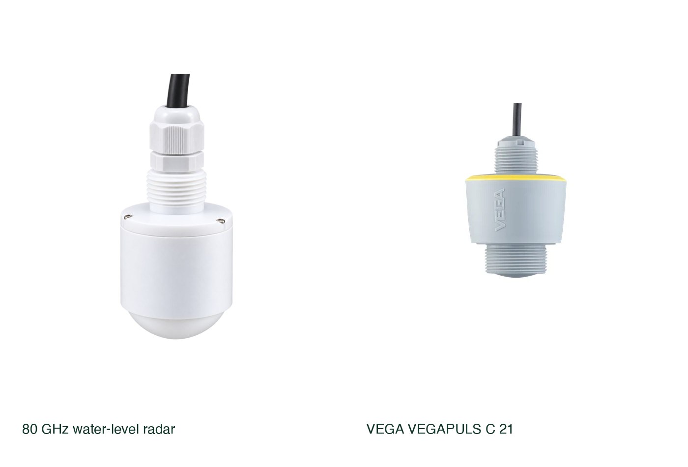
Deep Orbital 80 GHz water-level radar
A radar package supplied with a mounting bracket and a choice of housings. The published distance range makes it an option for water storage and reservoir measurements within a specified monitoring installation.
Confirm output protocol, power, near-sensor clearance and application accuracy for the supplied variant.
View product details ↗Cabled 80 GHz free-space radar
VEGA VEGAPULS C 21
A compact non-contact radar with a cabled connection. It keeps the measurement element above the water and offers interface variants for process and environmental loggers.
Mounting geometry, beam clearance and output variant determine suitability.
View product details ↗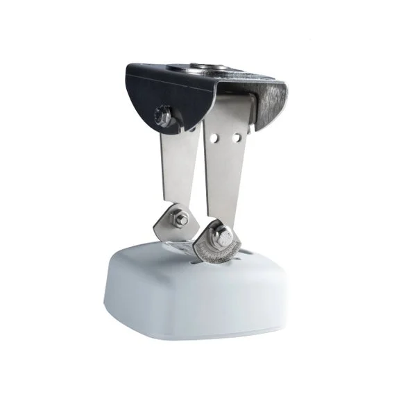
RLS500 SDI-12 model
OTT RLS 500
A radar instrument intended for water-level monitoring above an open surface. Its SDI-12 configuration fits compatible environmental data loggers.
Requires a stable mounting reference, power and logging infrastructure.
View product details ↗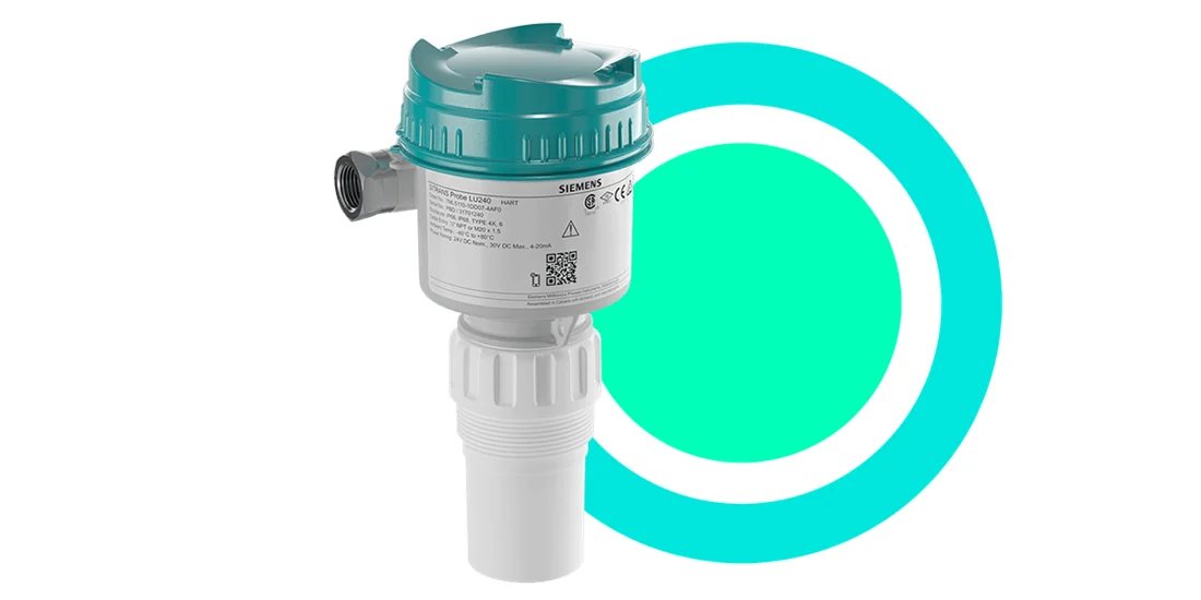
Selected 3, 6 or 12 m ultrasonic version
Siemens SITRANS Probe LU240
An ultrasonic transmitter with echo processing and a two-wire process interface. It offers an alternative to radar where its installation and surface conditions are suitable.
Acoustic path, foam, temperature and blanking distance need evaluation.
View product details ↗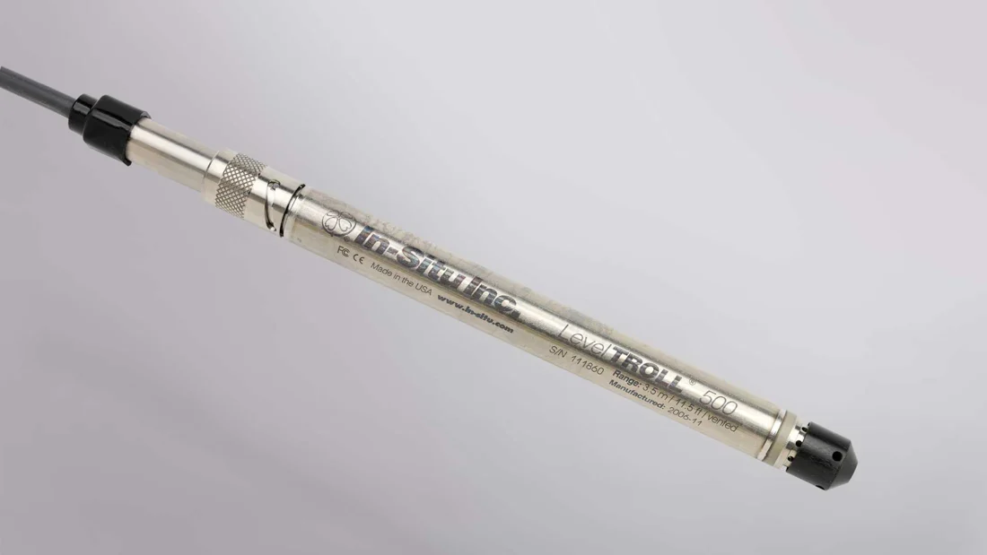
Vented pressure logger; selected pressure range
In-Situ Level TROLL 500
A compact titanium pressure logger that measures below the water surface. The vented arrangement compensates atmospheric pressure through the instrument and cable system.
Vented cable, desiccant, fixed suspension and pressure range need specification.
View product details ↗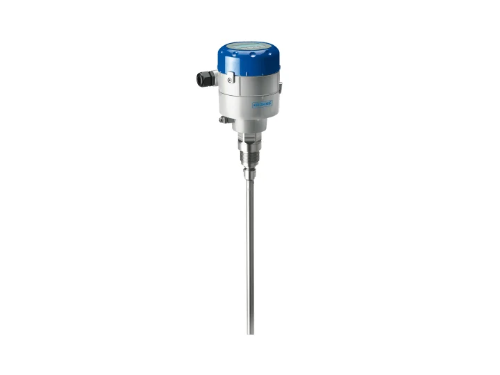
Guided radar TDR; selected rod, cable or coaxial probe
KROHNE OPTIFLEX 1100
A guided radar transmitter for basic liquid storage applications. Its probe-guided signal provides a different installation option from overhead free-space radar.
The probe contacts the process and needs compatible geometry and materials.
View product details ↗| Model | Measurement / role | Data connection | Coverage / installation |
|---|---|---|---|
| Deep Orbital 80 GHz water-level radar | Non-contact distance to a liquid or solid surface | Output and acquisition arrangement specified for the installation | Published maximum measurement distance 40 m |
| VEGA VEGAPULS C 21 | Non-contact liquid level | 4–20 mA/HART, Modbus or SDI-12 by version | Manufacturer range up to 20 m |
| OTT RLS 500 | Non-contact water level | SDI-12 to a compatible logger | Surface-water observation stations |
| Siemens SITRANS Probe LU240 | Non-contact liquid level | 4–20 mA/HART; optional Bluetooth adaptor | Up to 12 m by version; near-sensor blanking applies |
| In-Situ Level TROLL 500 | Water level, pressure and temperature | Onboard logging; compatible cable and optional telemetry | Submerged borehole or surface-water deployment |
| KROHNE OPTIFLEX 1100 | Liquid level along a contacting probe | Configured wired transmitter | Manufacturer family range 0.7–20 m |
The 80 GHz radar package is useful where a tank or reservoir installation needs a distance sensor and matching mounting bracket. A wider farm-monitoring design can use Pulse for supported instrument interfaces, with the radar output and selected gateway module specified together. Level histories can then be interpreted alongside irrigation records; the Pycno platform provides visual analysis and rule-based alerts for supported data sources.
Radar, ultrasound and hydrostatic pressure
Free-space radar transmits electromagnetic energy and identifies the returning surface echo. Depending on the instrument, distance is derived from travel time or a frequency-modulated signal. Antenna design and operating frequency influence beam geometry. A narrow beam can help avoid obstructions, but the installation still needs a clear measurement path and suitable alignment.
Ultrasonic instruments time an acoustic echo travelling through the air above the water. The speed of sound changes with air temperature, so compensation and installation conditions matter. Foam, condensation and disturbances along the acoustic path can weaken or alter the echo. A blanking distance defines the near-sensor region in which a usable level reading is not available.
Hydrostatic instruments measure pressure beneath the water surface. For a stable-density liquid, pressure increases with depth according to p = ρgh. Freshwater produces approximately 9.81 kPa per metre at ordinary conditions. Gauge-pressure systems compensate atmospheric pressure through a vent; absolute-pressure instruments require a suitable atmospheric record to separate water pressure from air pressure.
Guided radar sends a signal along a rod, cable or coaxial probe. The reflection from the liquid boundary provides a level measurement. Probe geometry, mounting clearances, deposits and vessel contents determine suitability. Its contact with the process makes its maintenance and mounting different from an overhead radar.
Reference points and mounting geometry
Place overhead sensors clear of filling streams, ladders, pipework and surfaces that can create competing echoes. Record the mounting reference and anticipated highest water level. The instrument must accommodate the full operating range and the required near-sensor clearance. Bracket stiffness matters because a moving mounting point changes the measurement reference.
Reservoir surfaces can move with waves and wind. Configure observation intervals and averaging around the intended decision: a pump-control response and a seasonal storage record do not require the same temporal detail. Preserve the unaveraged or short-interval record where transient conditions are important to diagnosis.
For submerged loggers, secure the installation against movement and inspect vented cables and desiccants as specified. Sediment can obstruct the pressure path or alter exposure. A change in suspension depth resembles a change in water level unless the reference position is documented. Temperature records help interpret environmental changes but do not correct an unknown mounting displacement.
Channel measurements and control applications
A channel-level reading becomes flow only through an appropriate hydraulic relationship, such as a calibrated weir or flume. The equation depends on the structure and installation. A water-level sensor above an arbitrary channel cannot independently determine discharge. Check approach conditions, submergence and the measurement location before applying a rating curve.
Tank refill control usually benefits from separate start and stop thresholds, giving a defined operating band. Alarm thresholds, overfill protection and the controller’s fault behaviour require their own specification. A communication-enabled level sensor supplies observations; a suitable local control system performs the pump or valve action.
Evaluate power demand, output protocol and logging arrangements together. SDI-12, Modbus and 4–20 mA variants are different connection choices. Select the variant supported by the receiving device and verify electrical requirements. Remote access normally needs a logger or telemetry device in addition to the measurement instrument.
From staff gauges to continuous measurements
Staff gauges and float-operated recorders provided water-level observations long before electronic transmitters. Pressure logging enabled compact submerged installations, while ultrasonic and radar systems made overhead measurements possible without a moving float. These methods still depend on the same basic discipline: a stable reference and a clear definition of the quantity recorded.
- Datum
- The reference elevation or zero against which water level is reported.
- Stage
- Water-surface elevation at a monitoring location, relative to its datum.
- Blanking distance
- The near-sensor zone excluded from valid ranging measurements.
- Rating curve
- A relationship used to estimate discharge from level under specified hydraulic conditions.
Questions about water-level instruments
Does radar measure reservoir volume directly?
It measures distance or level. Volume follows from an appropriate surveyed or calibrated level-volume relationship.
Can an ultrasonic transmitter use a radar installation unchanged?
Check its beam, blanking distance, temperature compensation and mounting requirements. A shared thread size does not guarantee an equivalent measurement geometry.
Can a level reading calculate irrigation-channel flow?
Only when a suitable structure or validated rating relationship connects that level to discharge. The sensor supplies one input to the hydraulic calculation.