Ground speed is an application measurement
A spreader or sprayer needs to know how much ground it covers, not simply how quickly a driven wheel turns. Wheel slip, tyre deformation and changing load can separate wheel rotation from forward movement. A ground-speed radar provides a contactless measurement of movement over the surface. Its output can drive a controller that adjusts material delivery as speed changes.
This is vehicle-mounted Doppler radar. It does not make a satellite radar image or measure the crop’s soil moisture. Position, obstacle detection and ground speed are different jobs even when all are discussed under agricultural radar. Check the intended measurement before comparing equipment.
Radar, wheel rotation and GNSS
Doppler radar transmits toward the ground and detects a frequency change in the returned signal caused by relative movement. Installation angle matters because the measured component of velocity depends on beam direction. Mounting vibration, moving vegetation and an unsuitable view of the surface can affect the signal. A clean bracket installation and a measured-distance calibration are part of the measurement system.
A wheel sensor counts magnets or passing teeth and converts rotation to distance through a calibration factor. It can provide a simple local signal but its relationship with ground distance changes with tyre and traction conditions. GNSS derives movement from satellite observations. It avoids a rotating-wheel measurement, but controller message format, output rate, start/stop behaviour and reception still need checking.
Compare sensing classes before comparing brands
Radar II and Radar III are two DICKEY-john models, not two independent manufacturers. The other entries below are wheel-rotation and GNSS architecture alternatives, not additional radar competitors. The NAV-900 needs a compatible receiving system and connection; it is not a drop-in pulse-output replacement for every older spray console. A replacement must match the controller’s signal input, wiring and calibration procedure.
Direct ground-speed radar
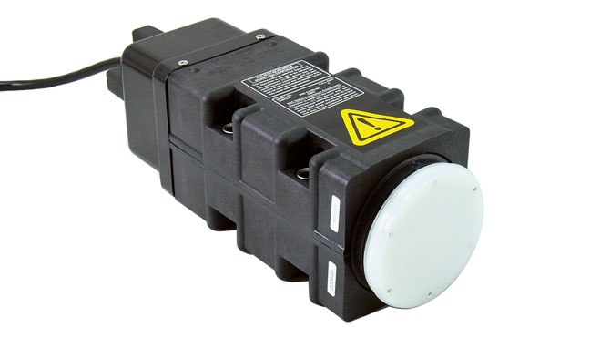
DICKEY-john Radar II
A directly listed agricultural ground-speed radar. Specify its harness and output configuration rather than assuming a radar connector is universal.
Mounting geometry, cable compatibility and distance calibration must match the console.
View product details ↗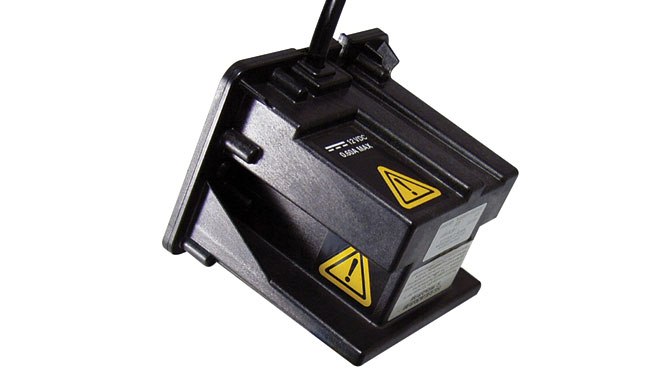
Compact direct ground-speed radar
DICKEY-john Radar III
A smaller DICKEY-john radar model that measures travel over the surface. It is an alternative model from the same manufacturer as Radar II.
Check stationary vibration behaviour and complete calibration after mounting.
View product details ↗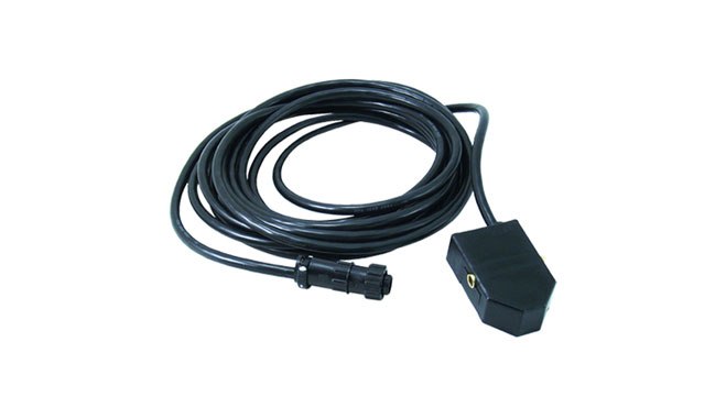
Wheel-rotation alternative; not radar
DICKEY-john Universal Speed Sensor
A magnetic wheel sensor kit. It offers a different sensing method from radar and needs a representative distance calibration.
Tyre changes and wheel slip affect the relationship with actual ground distance.
View product details ↗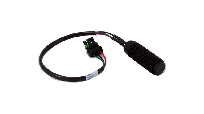
Rotation alternative; not radar
DICKEY-john Hall Effect Sensor
A rugged rotation sensor offered for agricultural equipment. A pulse count represents rotation until the controller relates it to distance or shaft speed.
Ground-speed use depends on the selected rotating part and calibration; slip can remain.
View product details ↗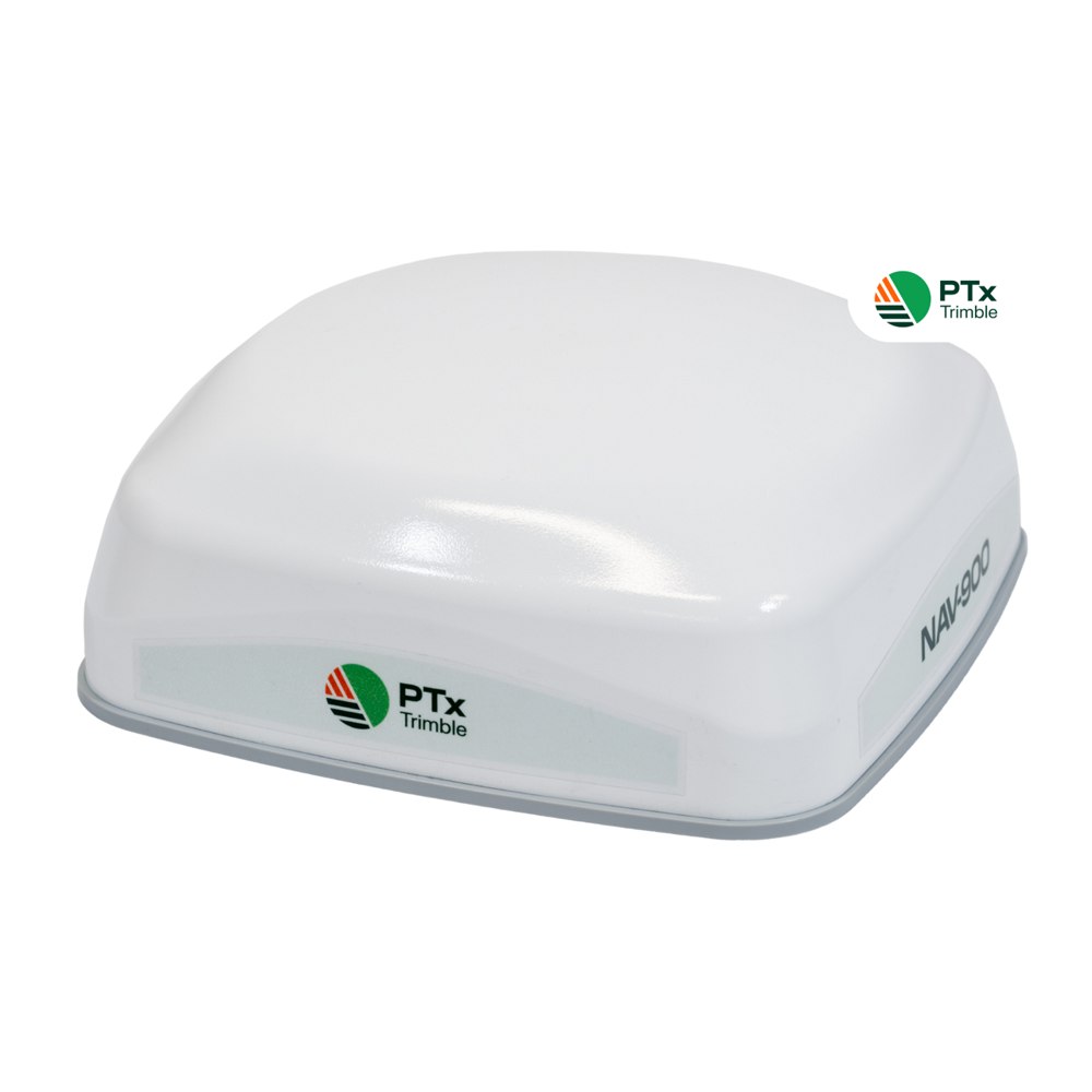
Guidance receiver/controller; matched GFX display
PTx Trimble NAV-900
A roof-mounted guidance controller supporting several correction options. Autoguidance requires a matched GFX display and a suitable steering system.
Budget for display, steering hardware and any correction subscription.
View product details ↗| Model | Measurement / role | Data connection | Coverage / installation |
|---|---|---|---|
| DICKEY-john Radar II | Doppler ground speed | Configured frequency/pulse output to compatible controller | Ground-viewing vehicle installation |
| DICKEY-john Radar III | Doppler ground speed | Configured frequency/pulse output to compatible controller | Ground-viewing bracket; forward or rear view per installation instructions |
| DICKEY-john Universal Speed Sensor | Wheel rotation converted to speed/distance | Pulse signal with console distance calibration | Wheel-rim magnets and axle-mounted pickup |
| DICKEY-john Hall Effect Sensor | Passing teeth, sprocket or lug movement | 12 V sensor with square-wave signal output | Machine rotation sensing with suitable mounting gap |
| PTx Trimble NAV-900 | GNSS position and guidance control | GFX display and selected corrections; compatible output connection | Roof mounting; compatible steering equipment required |
Check mounting and pulse scaling
The DICKEY-john installation instructions call for a vibration check before securing the cable: the stationary machine should not show ground speed as engine speed changes. Follow the model’s permitted mounting orientation, height and angle, keep the beam clear, and protect wiring from abrasion and heat. Moving the bracket after calibration can change the measurement geometry.
A controller may expect wheel pulses, radar pulses, a serial speed message or speed over a vehicle bus. Similar plugs do not prove that supply voltage, signal level and pin assignment agree. Record the selected sensor type and calibration constant. Travel a measured distance using the controller’s specified procedure, then compare readings through slow movement, acceleration, stopping and reversing where supported.
Why a small speed error matters
Consider a sprayer delivering a measured 60 litres per minute through a 20 metre working width at 10 kilometres per hour. The calculated application rate is 600 × 60 ÷ (20 × 10), or 180 litres per hectare. This example assumes uniform delivery and effective width. A controller using an incorrect speed changes its demand even when the flow sensor itself is accurate.
Check rate control across the operating range, including headland acceleration. Correcting speed alone cannot fix worn nozzles, a biased flow meter or the wrong section width. Review the speed input alongside the application system in the variable-rate guide.
Long-standing instruments, different interfaces
DICKEY-john’s Hall Effect quick-reference document is dated May 2005, and its Radar III installation revision is dated January 2017. These establish documented agricultural sensing approaches before today’s integrated guidance displays. The currently listed product pages still offer those sensing classes. A document date identifies that revision; it does not establish a product’s first release date or local stock availability.
Speed sensing terminology
- Doppler shift
- A change in received frequency caused by relative movement.
- Slip
- The difference between wheel-derived travel and actual travel over the ground.
- Pulse scaling
- The configured relationship between counted electrical pulses and distance.
- Latency
- The delay between movement and the value available to the controller.
Can radar replace a failed wheel sensor?
Only after verifying the console’s supported sensor input and the complete cable arrangement. Reconfigure and recalibrate the console for the replacement. A radar may remove wheel-slip error while introducing different mounting and surface sensitivities, so verify performance under the field conditions in which the application will run.